Instant download New Holland Cnh Diesel Engine Service Repair Workshop Manual. This manual content all service, repair, maintenance, troubleshooting procedures for New Holland Cnh Diesel Engine.
All major topics are covered step-by-step instruction, diagrams, illustration, wiring schematic, and specifications to repair and troubleshoot. With this factory service repair manual on hand can easily help you with any repairs that you may need for your New Holland Cnh Diesel Engine.
Machine model :
New Holland Cnh Diesel Engine
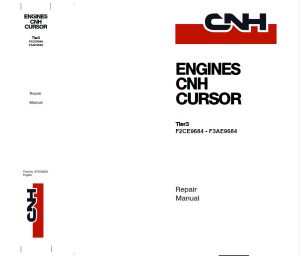
Tier3 F2CE9684 – F3AE9684
Print No. 87476950A
The following engines are presented to the service manual:
Cursor F2C Engines:
F2C89684A*E009 F2CE9684B*E001
F2CE9684C*E001 F2CE9684D*E001
F2CE9684C*E002 F2CE9684E*E002
F2CE968P*E007 F2CE968P*E008
F2CE968N*E005 F2CE968P*E006
Cursor F3A Engines:
F3AE0684L*E906 F3AE0684P*E906 F3AE0684P*E905 F3AE0684S*E908 F3AE0684N*E907
Manual Covers:
SECTION 1 GENERAL SPECIFICATIONS
TECHNICAL CODE
TECHNICAL DESIGNATION
VIEWS OF THE ENGINE (for types: F2CE9684A*E004 –
F2C89684A*E009 – F2CE9684B*E001 –
F2CE9684C*E001 – F2CE9684D*E001 –
F2CE9684C*E002 – F2CE9684E*E002 –
F2CE968P*E007 – F2CE968P*E008)
VIEWS OF THE ENGINE (for types: F2CE9684L*E005 –
F2CE968N*E005 – F2CE968P*E006)
LUBRICATION DIAGRAM
– Oil pump
– Overpressure valve
– Oil pressure control valve
– Heat exchanger
ENGINE OIL FILTER
– Characteristics
– Lock torques
– Installation rule
– Filter by-pass valve
– Replacing oil filter cartridge
– Dismantling
– Refitting
– Oil fume recycle (Blow-by)
COOLING
– Description
– Operation
– Water pump
– Thermostat
TURBOCHARGING
EGR EXHAUST GAS RECYCLE SYSTEM
INTERNAL EGR OPERATING ON SUCTION
VALVES
SECTION 2 FUEL
SUPPLY
FUEL SUPPLY DIAGRAM
MECHANICAL SUPPLY PUMP
– Normal operating conditions
– Overpressure condition at outlet
– Drain conditions
CP3 HIGH-PRESSURE PUMP
HIGH-PRESSURE PUMP – INSIDE STRUCTURE
– Operating principle
– Operation
RAIL (PRESSURE ACCUMULATOR)
– Electroinjector
SECTION 3 INDUSTRIAL APPLICATION
CLEARANCE DATA
PART ONE -MECHANICAL COMPONENTS
ENGINE DISASSEMBLY ON BENCH
ASSEMBLY
– High pressure pump installation
ENGINE FLYWHEEL
– Engine flywheel installation
– Camshaft installation
TIMING CAMSHAFT AND FLYWHEEL USING
SPECIAL TOOL
– Timing camshaft
– Timing flywheel
TIMING CAMSHAFT AND FLYWHEEL WITHOUT
SPECIAL TOOL
– Timing camshaft
– Timing flywheel
– Intake and exhaust rocker arm clearance
adjustment
ENGINE ASSEMBLY COMPLETION
PART TWO – ELECTRICAL EQUIPMENT
– Components on the engine F2C
– Engine cable
– EDC 7 UC31 control unit pin-out
– EDC 7 UC31 electronic control unit
– EDC control unit PIN-OUT
– Electroinjectors
– Engine coolant temperature sensor
– Fuel temperature sensor
– High pressure pump (pressure regulator)
– Flywheel pulse transmitter
– Distribution pulse transmitter
– Fuel pressure sensor on rail
– Alternator
(i excluded types: F2CE9684C*E002 –
F2CE9684E*E002 – F2CE9684H*E003)
– Alternator (for types: F2CE9684C*E002 –
F2CE9684E*E002)
– Alternator (for type: F2CE9684H*E003)
– Starting motor
EDC SYSTEM FUNCTIONS
PART THREE – TROUBLESHOOTING
CNH — EST DIAGNOSTIC TOOL
FAULT CODES
TROUBLESHOOTING
PART FOUR – MAINTENANCE PLANNING
MAINTENANCE
– Maintenance services chart
CHECKS AND/OR MAINTENANCE WORK
OFF-PLANE OPERATIONS
SECTION 4: OVERHAUL AND TECHNICAL SPECIFICATIONS
GENERAL CHARACTERISTICS
ASSEMBLY CLEARANCE DATA
ENGINE OVERHAUL
ENGINE REMOVAL AT THE BENCH
REPAIR OPERATIONS
CYLINDER BLOCK
– Checks and measurements
CYLINDER LINERS
– Replacing cylinder liners
– Removal
– Fitting and checking protrusion
CRANKSHAFT
– Measuring main journals and crank pins
PRELIMINARY MEASUREMENT OF MAIN AND BIG
END BEARING SHELL SELECTION DATA
– Selecting the main and big end bearing shells
– Replacing the timing control gear and the oil pump
– Checking main journal installation clearance
– Checking crankshaft end float
PISTON-CONNECTING ROD ASSEMBLY
– Removal
– Measuring the diameter of the pistons
– Conditions for correct gudgeon pin-piston coupling
– Piston rings
CONNECTING ROD
– Checking connecting rod alignment
– Mounting the connecting rod – piston assembly
– Mounting the piston rings
– Fitting the connecting rod-piston assembly into the piston liners
– Piston protrusion check
– Checking the planarity of the head on the cylinder block
CYLINDER HEAD
– Dismounting the valves
– Checking assembly clearance of big end pins
VALVE
– Removing deposits and checking the valves
VALVE GUIDES
– Replacing of valve guides
– Replacing – Reaming the valve seats
REPLACING INJECTOR HOLDER CASES
– Removal
– Checking protrusion of injectors
TIMING GEAR
– Camshaft drive
– Intermediate gear pin
– Idler gear
– Twin idler gear
– Replacing the bushings
– Camshaft
– Checking cam lift and pin alignment
– Bushes
– Fitting the valves and oil seal ring
– Removal
– Fitting
VALVE SPRINGS
– Use beater to change bushings
ROCKER SHAFT
– Rocker
– Shaft
TIGHTENING TORQUES
SECTION 5: TOOLS
AND MORE…
SPECIFICATION:
Pages:355
Format: PDF
Language: English
Compatible: Win/Mac
All pages are printable, so run off what you need & take it with you into the garage or workshop.
Save money $$ by doing your own repairs! It make it easy for any skill level with these very easy to follow, step-by-step instructions!
Instant download means no shipping cost or waiting for a CD to arrive in the mail…you will receive this manual today via instant download on completion of payment via our secure payment processor. We accept all major credit/debit cards/paypal.
Instant download! Thank you for visiting!


